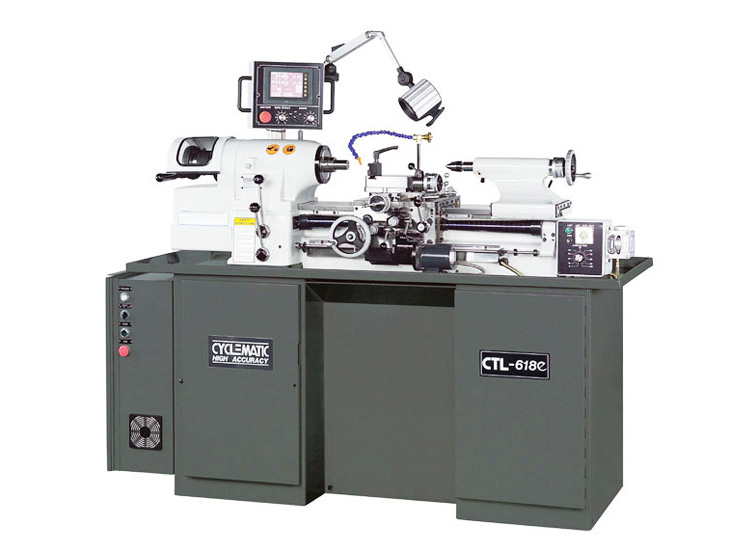
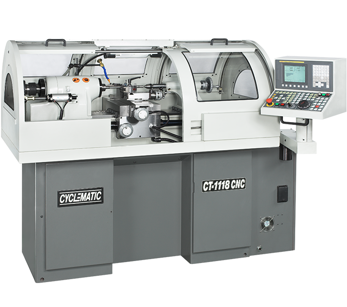
CT-606CNC Gang-Type CNC toolroom lathes which comes with FANUC Control and has gang-type tooling and linear motion guides that enables you to get the job done faster. Tool holders are not included. |
- Special features
- Specification
- Operation manual
- Optional
![]() |
||||||||||||||||||||||||||||||||||||||||
![]() |
||||||||||||||||||||||||||||||||||||||||
![]() |
||||||||||||||||||||||||||||||||||||||||
![]() |
||||||||||||||||||||||||||||||||||||||||
|

|
||||||||||||||||||||||||||||||||||||||||
| MODEL | CT-606CNC | |
| Maximum Swing | 200 mm | |
| Maximum Turning Diameter | Ø 150 mm (Ø 6") | |
| Bar stock Diameter (5C collet) | Ø27 mm (Ø1-1/16") | |
| Hole Through Spindle | Ø31.75mm (Ø1-1/4") | |
| CNC Controller | FANUC (STANDARD) | |
| Spindle speeds (Variable) | 50~4000 R.P.M. (3HP) | 50~6000 R.P.M. (5HP) |
| Spindle Nose I.D./O.D. | 5C (10°) / 4° Taper | |
| Quick-action compound slide travel | 2.5 mm (0.1") | |
| Chuck Diameter | Ø150 mm (Ø6") | |
| Maximum X-axis Travel | 200 mm (7.874") | |
| Maximum Z-axis Travel | 150 mm (5.906") | |
| Rapid Traverse | 20 M/min | |
| Inverter Spindle Motor | 3 HP or 5HP | |
| X,Z-Axis Servo Motor | X : ß2 / Z : ß2 | |
| Coolant Pump | 1/4 HP | |
| Net/Gross weight | 2,530/2,750 lb. (1,150 / 1,250 kg.) | |
| Machine packing dimension | 2,300 × 1,200 × 1,910 mm (87" × 44" × 85") | |
| All dimensions, specifications and machine appearance are subject to change without prior notice. | ||
![]() |
|
The model CT-606CNC series machine is built for easy and safe operation and excellent manufacturing of work in process. The machine is built with high quality material, and carefully to exacting standards that guarantee the life, economical use, accuracy, and minimum maintenance of the machine. This manual is an introduction to the CYCLEMATIC model CT-606CNC HIGH ACCURACY TOOL ROOM LATHE. It is used for installation, operation and servicing of the CT-606CNC CYCLEMATIC MACHINES. Also, for fast reference, because it is necessary to make minor adjustments or do preventive maintenance. (For personnel and operators who deal with the CT-606CNC machine.) |
|
Place Two Levels on Slide Way ![]() Figure A CT-606CNC |
|
|
|
![]() Figure C – Lifting machine |
|
| Lifting machine, arrange rope or cable as shown in (Figure C), and check to see if the correct balance has been obtained. Then insert pads of soft cloth between the edges of the rope and machine. The net weight of this machine is approx 1000 kgs (2200 lbs). So the rope or cable must be rated at 3000 lbs capacity. | |
|
|||||||
|
|||||||
Proper lubrication supplied carefully, will maintain the life and performance of the machine for a long period. Therefore, lubricate the machine with a high quality lubricant. Fill with Mobil Vactra Oil No.2 or equivalent in oil reservoir and check oil level usually, please keep oil more then "Min" line (see figure 3). 1. HEADSTOCK LUBRICATION |
![]() Figure 3-Automatically Oil Pump |
Running the machine with the collet closer and not having a collet locked in place will damage the collet closer. Remove the collet closer when using chucks, face plates, or spindle nose type fixtures. The collet closer should be removed often for cleaning to prevent loading of chips between collet closer tube and inside of spindle at rear and collet threads. Removal method is:Pull out pin ”L” (Figure 4). Slide draw tube out of the spindle. Do not turn the adjusting nut “N” (Figure 4). It is keyed to the spindle. To remove slide it off the end of the spindle. Do not remove collet closer by removing screw “S” (Figure 4), this screw has been adjusted at the factory for proper operation of the collet closer. |
![]() Figure 4-Collet Closer Removal |
Before replacement of the closer, clean inside of the headstock spindle and outside diameter at rear of spindle where Adjusting Nut “N” (Figure 5) is located. Apply a film of light oil on rear of spindle Do not force Adjusting Nut "N" (Figure 5) on spindle. If Adjusting Nut "N" (Figure 5) fits to tight, remove and check for burrs or scratches, then replace. Clean collet closer tube inside and out apply a film of light oil on slip surface "T" (Figure 5) of the collet closer tube, replace collect loser and insert Link Pin “L” (Figure 5). |
![]() Figure 5-Collet Closer Removal |
|
|||||
|
|||||
Run spindle at approximately 1000 rpm and stop the spindle. This is done to equalize belt tension. Loosen lock nut "N" (Figure 8) 19mm wrench. Turn adjusting screw "P" (Figure 8) 6mm socket head wrench clockwise to tighten belts. Stop machine and check belt tension, there should be approx. 25.4mm (1") of play in belt. |
![]() Figure 8-Belt Adjustment |
When collet close, the handle "A" (Figure 9) will go ← way. |
Figure 9-Air Collet Closer |
Air flow in the triangle |
![]() Figure 10-Air F/R.L Unit |
Open "A" (Figure 11) and fill with Mobil Vactra Oil No.2 or equivalent in oil reservoir when the oil line lower then min line. |
![]() Figure 11-Automatically Oil Pump |
Step the foot step air collet closer for open/close collet. |
![]() Figure 12 Foot Step Air Collet Closer |
Please fill the coolant water up to max line (Figure 13) , if coolant water less then min line may damage the coolant pump . Change the coolant water , please take off the screw A , the waste water will out of hole. |
![]() Figure 13-Coolant Tank |
When red light shine , it mean machine have some alarm massage or some problem . When yellow light shine , it mean work complete. When green light shine , it mean work is doing right now. |
![]() Figure 14 – Work situation light |
To increase coolant water please push it this way ←. To decrease it goes to this way →. |
![]() Figure 15-Coolant |
| Press "LIGHT" key to open or close working lamp. | ![]() Figure 16-Working Lamp |
| CT-606 CNC Lathe machine have RS232 or CF card to connect with FANUC controller . Also have 110v plug for Note Book. | ![]() Figure 17-RX232 |
|
||||||
1. Switch on main power switch. |
|
| ※THE SPINDLE SHALL ROTATE IN THE DIRECTION OF AN ARROW WAY, WHICH IS SHOWING IN THE VICINITY OF THE SPINDLE. IF THE SPINDLE IS ROTATING IN THE OPPOSITE DIRECTION, PLEASE TURN OFF POWER AND OPEN ELECTRICAL BOX AND SWITCH ANY 2 WIRED, AFTER THAT THE SPINDLE SHOULD BE ROTATE CORRECT WAY. | |
A) POWER OFF: |
![]() |
| B) POWER ON: Button for power on CNC controller. |
![]() |
| C) CYCLE START: Button for cycle start the program. |
![]() |
| D) FEED HOLD: Button for hold feed rate or stop machine moving. |
![]() |
| E) FEED RATE CONTROL: Switch for feed rate percentage. |
![]() |
| F) PANEL HAND WHEEL: Turn the switch for X and Z axis, X1= move 0.001 MM, X10 = move 0.01 MM, X100 = move 0.1 MM. ( If order machine side hand wheel, use F1 to switch standard hand wheel or machine side hand wheel ) . |
![]() |
| G) EMERGENCY STOP: For any emergency condition, press the button to stop all the moving elements immediately. |
![]() |
| 1) DNC: Use RS232C connect with PC . sometimes file too big to save into the FANUC controller , use DNC to transfer file also doing the work in same time . |
![]() |
| 2) EDIT : Edit program file to the FANUC controller . |
|
| 3) AUTO: Select the AUTO + CYCLE START button for run the program . |
|
| 4) MDI: Select the MDI for edit short machine code or one time program edit, after press cycle start those code or program file will disappear(For more info please see Fanuc operator's manual) ps. Change Fanuc parameter should be in MDI mode , otherwise it won't effect. |
|
| 5) HANDLE: Select the HANDLE for use hand wheel . For panel side hand wheel can select x or z axis . ( If customer order machine side hand wheel , use F1 to switch panel side hand wheel or machine side hand wheel .) |
|
| 6) JOG: Select the JOG move X or Z axis, for use this function please select JOG and press (For more info please see Fanuc operator's manual) also change feed rate control can be change the JOG speed. |
|
| 7) RAPID : Select the RAPID to fast move X or Z axis , for use rapid function please select RAPID and press |
|
| 8) ZRN: Select the ZRN to return the X and Z axis origin, for use this function Select ZRN + |
|
| 9) POSITIVE OF X AXIS: To use with JOG , RAPID , ZRN . |
![]() |
| 10) NEGATIVE OF X AXIS: To use with JOG , RAPID , ZRN . |
![]() |
| 11) NEGATIVE OF Z AXIS: To use with JOG , RAPID , ZRN . |
![]() |
| 12) POSITIVE OF Z AXIS: To use with JOG , RAPID , ZRN . |
![]() |
| 13) SPECIAL FUNCTION F1: Use |
![]() |
14) OT RELEASE: |
![]() |
| 15) SINGLE BLOCK: Use this function for running program by single block, if want to move on next line, have to press cycle start every time. |
![]() |
| 16) OPITIONAL STOP: Use this function for optional stop the program. Light's on, when program read to Mo1, machine will stop, need press cycle start to let program continue. |
![]() |
| 17) WORK LAMP ON/OFF: Press the key to turn on/off the working lamp. Ps. When lamp lights on mean's light will on |
![]() |
| 18) BLOCK SKIP: Use this function for block skip program. When front of machine code add / , also the block skip light are on , it's mean controller will skip this code line . |
![]() |
| 19) DRY RUN: Use this function for dry run machine, ignore any feed rate. |
![]() |
| 20) MACHINE LOCK: Use this function for lock machine, only run the program, machine did not move. after use machine lock, must HOME again. If not may cause machine damage . Use this function for lock machine, only run the program, machine did not move. |
![]() |
| 21) COOLANT AUTO: Use this function for auto coolant, use M8、M9 code to open/close coolant pump. |
![]() |
| 22) COOLANT ON: Use this function for manual coolant pump, press button to open/close coolant pump. |
![]() |
| 23) PROGRAM EDIT LOCK : To lock the edit program, make people can't program the code by edit or change it. |
![]() |
| 24) RAPID TRAVERSE OVERRIDE: This selection use for rapid low speed. Also home speed can control. |
![]() |
| 25) RAPID TRAVERSE OVERRIDE 25%: This selection use for rapid 25% speed. also home speed can control, (recommend use this speed to home.) |
|
| 26) RAPID TRAVERSE OVERRIDE 50%: This selection use for rapid 50% speed. also home speed can control. |
|
| 27) RAPID TRAVERSE OVERRIDE 100%: This selection use for rapid 100% speed. |
|
| 28) SPINDLE SPEED OVERRIDE: This selection use for decrease spindle speed or increase spindle speed . Normally this selection will select at 100% . |
![]() |
| 29) CLOCKWISE SPINDLE: This button use for clockwise spindle, when light on telling you spindle clockwise right now. (For lathe machine clockwise spindle should go |
![]() |
| 30) STOP SPINDLE: This button use for stop spindle . |
![]() |
| 31) COUNTER CLOCKWISE SPINDLE: This button use for counter clockwise spindle, when light on telling you spindle is counter clockwise right now. |
![]() |
| 32) JOG SPINDLE: This button use for jog the spindle when you press this button spindle will goes really slowly by clockwise. |
![]() |
33) LUBE ALARM: |
![]() |
| 34) NC ALARM: When light on, it mean the CNC have some problem, press penal key to read massage after finish reading, press reset to remove massage and light. |
![]() |
| 35) MOTOR ALARM: When left corner red light on, it mean the motor have some problem , please check it. |
![]() |
| 36) CHUCK CLOSE: When light on, it mean chuck is close, if light not flash on, it mean chuck is open . when chuck open you can't rotate the spindle. |
![]() |
| 37) TURRET: Optional Unit This function key can manual change tool. |
![]() |
| 38) X AXIS HOME : When light on , it mean X axis has been home. After move x axis the light will off . |
![]() |
| 39) Z AXIS HOME : When light on , it mean Z axis has been home. After move Z axis the light will off . |
![]() |


Figure 9-Air Collet Closer


